Dear Reader,
This is for Poynty
Thanks for the efforts here. But you've not given us a replication. I don't think that PSpice can manage it - quite frankly - unless and until it can trace the battery voltage as a direct product of the current through the shunt resistor. It really needs to show that second order phase shift as you term it. Also. See if you can do something where the resonance ramps up rather than down as it progresses.
Poynty. It bothers me that you're so easily satisfied with an explanation. Your reasons are wrong. Transistor Zener very much in tact. And there's no variation if and when we put the probes directly on the battery terminals. And you're rather keen on using your standard DMM. If you put the setting to AC it will show that negative battery voltage. But it never exceeds zero to the extent that you've shown it. Look again at our traces. The battery voltage 'flirts' with zero at best - and only now and then does it actually breach that level - and then only by a fraction.
Kindest regards,
Rosie
I keep trying to post the link. It's not taking it. Here's the best I can manage.
http://www.overunityresearch.com/index.php?topic=13.msg10980;topicseen#msg10980
PS - it seems that I've again exposed my 'amateurish' status. LOL. MH - take it as read that this is the fact. However, to clarify that AC setting of your standard DMM - here's what's meant. Poynty insists that we do not need those sophisticated DSO's. I needed to cater to his preference. (another edit) As well as putting the DSO probes closer to the battery terminals - I also used a standard DMM on the battery, putting these probes directly on the battery terminals. And on a DC setting it's rock solid at a given value. On an AC setting, interestingly, it moves all over the place - even into negative - but never to the extent of those voltages that PSpice shows.
Regards,
R
Friday, February 18, 2011
Thursday, February 17, 2011
58 - another general update on the planned demonstration
Dear Reader
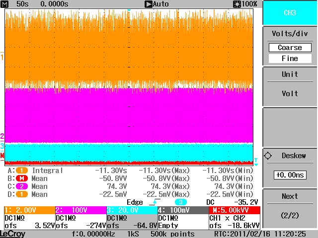
I am not sure that the waveform can be duplicated on a simulator. I'd be interested to see if this is, in fact, possible. Perhaps our Poynty can give this a go. I am delighted, in any event, to see that it's being denied on the basis of a faulty IRFPG50. It's an intriguing number. I think, in fairness, the person that first found this negative triggering was Aaron Murakami - and that by accident. It's just unfortunate that to see the full effect one actually needs a really broad band DSO. And to hold the pattern one needs something a little more reliable than a 555. In any event, the results are unequivocal. And on this particular setting it shows infinite co-efficient of performance. I think Harvey, for one, denied the general effect on the basis of the temporary nature of the data capture. There was an implicit suggestion that the data - over a short period - was not, necessarily, representative. That 50 second number should put that argument to bed.
I can assure you all that the resonance sustains itself. At slower frequencies we get an identical pattern but with a far longer interval of resonance. Of interest is that this seems to be a rock solid resonating condition. Very intriguing - from so many levels. I'm still of the opinion that the only possible explanation of this - dare I say it - is in that 'thinking' that preceded the experiment. But I'm open to correction. Time alone will tell. And I'm most interested to read of some kind of serious analysis applied. If, as I recommend - one simply allows a material property and a dual charge in the current then all is very easily reconciled. Hopefully that explanation will be considered - eventually.
Meanwhile - just a quick update on the demonstration. We will be sending invitations to all our campuses for a demo to be held on Saturday the 12th of March, 2011 - to view the demonstration and accredit the results. In order to 'fit in' with the onerous demands of those heavy academic timetables, we'll also be offering optional more private viewings during the week from the 11th through to the 14th for those who can't make it on Saturday. But we'll only be sending out the invitations during the course of next week. The Saturday viewing will be the official demo and hopefully, we'll be able to get a reporter there.
This will give me the time to settle the variations that we would also need to show and it should allow more time to collate yet more data. I also have to list those many questions that are still outstanding. The most intriguing is that the phenomenon is definitely dependent on the resonating condition of the circuit. And while the resonance is replicable - it is also both elusive and subtle. There is much to be researched. And it needs to be left in the capable hands of serious researchers. Hopefully the demos will be the required catalyst. Certainly I hope that we can prepare a paper on this prior to that demonstration.
So dear Reader. I trust that we can get this to the desks of our learned and revered that they can determine what gives. When and if I see that this is being constructively managed - then I can bow out. It really only needs the trained academic mind to resolve this. And my own contributions here are really and only in as much as I have - I hope - pointed to those questions especially as it relates to the material property of current itself.
Kindest regards,
Rosemary
I am not sure that the waveform can be duplicated on a simulator. I'd be interested to see if this is, in fact, possible. Perhaps our Poynty can give this a go. I am delighted, in any event, to see that it's being denied on the basis of a faulty IRFPG50. It's an intriguing number. I think, in fairness, the person that first found this negative triggering was Aaron Murakami - and that by accident. It's just unfortunate that to see the full effect one actually needs a really broad band DSO. And to hold the pattern one needs something a little more reliable than a 555. In any event, the results are unequivocal. And on this particular setting it shows infinite co-efficient of performance. I think Harvey, for one, denied the general effect on the basis of the temporary nature of the data capture. There was an implicit suggestion that the data - over a short period - was not, necessarily, representative. That 50 second number should put that argument to bed.
I can assure you all that the resonance sustains itself. At slower frequencies we get an identical pattern but with a far longer interval of resonance. Of interest is that this seems to be a rock solid resonating condition. Very intriguing - from so many levels. I'm still of the opinion that the only possible explanation of this - dare I say it - is in that 'thinking' that preceded the experiment. But I'm open to correction. Time alone will tell. And I'm most interested to read of some kind of serious analysis applied. If, as I recommend - one simply allows a material property and a dual charge in the current then all is very easily reconciled. Hopefully that explanation will be considered - eventually.
Meanwhile - just a quick update on the demonstration. We will be sending invitations to all our campuses for a demo to be held on Saturday the 12th of March, 2011 - to view the demonstration and accredit the results. In order to 'fit in' with the onerous demands of those heavy academic timetables, we'll also be offering optional more private viewings during the week from the 11th through to the 14th for those who can't make it on Saturday. But we'll only be sending out the invitations during the course of next week. The Saturday viewing will be the official demo and hopefully, we'll be able to get a reporter there.
This will give me the time to settle the variations that we would also need to show and it should allow more time to collate yet more data. I also have to list those many questions that are still outstanding. The most intriguing is that the phenomenon is definitely dependent on the resonating condition of the circuit. And while the resonance is replicable - it is also both elusive and subtle. There is much to be researched. And it needs to be left in the capable hands of serious researchers. Hopefully the demos will be the required catalyst. Certainly I hope that we can prepare a paper on this prior to that demonstration.
So dear Reader. I trust that we can get this to the desks of our learned and revered that they can determine what gives. When and if I see that this is being constructively managed - then I can bow out. It really only needs the trained academic mind to resolve this. And my own contributions here are really and only in as much as I have - I hope - pointed to those questions especially as it relates to the material property of current itself.
Kindest regards,
Rosemary


Wednesday, February 16, 2011
57 - waveforms - 180 degrees out of phase
Dear Reader,
I took the trouble to do a series of downloads just to compare values. I'll download some of those pictures but need to do a detailed schedule of results. Note that the values remain negative - proof of infinite co-efficient of performance and our resistor is dissipating plus/minus 6 watts in temperature. Just out of interest that beautiful waveform entirely disappears at below 36 volts from the supply.
Kindest regards,
Rosemary
CHANNEL 1 shunt @ 0.25 Ohm
CHANNEL 2 battery
CHANNEL 3 gate
CHANNEL 4 math trace product of channel 1 and 2


I took the trouble to do a series of downloads just to compare values. I'll download some of those pictures but need to do a detailed schedule of results. Note that the values remain negative - proof of infinite co-efficient of performance and our resistor is dissipating plus/minus 6 watts in temperature. Just out of interest that beautiful waveform entirely disappears at below 36 volts from the supply.
Kindest regards,
Rosemary
CHANNEL 1 shunt @ 0.25 Ohm
CHANNEL 2 battery
CHANNEL 3 gate
CHANNEL 4 math trace product of channel 1 and 2


56 - on presumptions and poynted poyntifications
Dear Reader,
I really need to answer Poynty and his brave if somewhat intellectually challenged cohorts. In any event - here's a quick response just to assure them that I still read there and before I get back on topic.
Poynty Point, I will pass on your offer to debunk - but thank you. I have infinitely more confidence in the expertise of real experts. And they abound in our own country. And God willing, they may yet have a look in and check out the facts for themselves. With respect, and unlike you, they do not offer gratuitous abuse and nor, thankfully, do they apply the level of editing that you seem to enjoy in your own data capture - ably asssisted as you are by your excessive use of a simulator. In any event I rather rely on their professionalism and very much doubt that they'd indulge in the character attack that you seem to actively encourage. You should exercise more restraint in this mission of yours to DENY THESE OUR RESULTS. That way one could still accuse you of impartiality. Do you really think that that staff memebers here do not have the required expertise to establish whether or not a result is due to a badly soldered joint - or to incorrect probe positioning - or to inadequate data capture??? What are you thinking Poynty?
MileHigh, you are right and yet you are wrong. We have lost that lossy parasitic Hartley Effect and replaced it exclusively with a stable harmonic - the same one that did so much good on our replicated tests. That's courtesy the functions generator. Far more stable. I wish that it was as readily available and as inexpensive as the 555. But there you go. Never did anyone claim that the chaotic oscillation increased the efficiency. But as it's you, then I can understand your need to fabricate the facts to try and highlight whatever you can manage. Not so long ago you were crowing that we could not manage a demonstration at all. I just wonder where your next attack will come. Possibly you'll claim that we need to replace the battery with a capacitor. That'll be a new one for the books. How aout it Milesupintheclouds?
And Ion and Humbugger and Grumpy and even WaveWatcher. If you were less spiteful I could still consider you to be men. As it is I don't.
Kindest as ever,
Rosie
I really need to answer Poynty and his brave if somewhat intellectually challenged cohorts. In any event - here's a quick response just to assure them that I still read there and before I get back on topic.
Poynty Point, I will pass on your offer to debunk - but thank you. I have infinitely more confidence in the expertise of real experts. And they abound in our own country. And God willing, they may yet have a look in and check out the facts for themselves. With respect, and unlike you, they do not offer gratuitous abuse and nor, thankfully, do they apply the level of editing that you seem to enjoy in your own data capture - ably asssisted as you are by your excessive use of a simulator. In any event I rather rely on their professionalism and very much doubt that they'd indulge in the character attack that you seem to actively encourage. You should exercise more restraint in this mission of yours to DENY THESE OUR RESULTS. That way one could still accuse you of impartiality. Do you really think that that staff memebers here do not have the required expertise to establish whether or not a result is due to a badly soldered joint - or to incorrect probe positioning - or to inadequate data capture??? What are you thinking Poynty?
MileHigh, you are right and yet you are wrong. We have lost that lossy parasitic Hartley Effect and replaced it exclusively with a stable harmonic - the same one that did so much good on our replicated tests. That's courtesy the functions generator. Far more stable. I wish that it was as readily available and as inexpensive as the 555. But there you go. Never did anyone claim that the chaotic oscillation increased the efficiency. But as it's you, then I can understand your need to fabricate the facts to try and highlight whatever you can manage. Not so long ago you were crowing that we could not manage a demonstration at all. I just wonder where your next attack will come. Possibly you'll claim that we need to replace the battery with a capacitor. That'll be a new one for the books. How aout it Milesupintheclouds?
And Ion and Humbugger and Grumpy and even WaveWatcher. If you were less spiteful I could still consider you to be men. As it is I don't.
Kindest as ever,
Rosie
55 - not so brief - many moments in time - in fact, 50 seconds worth
Dear Reader,
Here's a sight for sore eyes. Fifty seconds of pure magic in one fell swoop. Enjoy. Much more to follow - but this little doozy took a cool 18 minutes to upload. It needs framing.
Kindst regards,
Rosie

Here's a sight for sore eyes. Fifty seconds of pure magic in one fell swoop. Enjoy. Much more to follow - but this little doozy took a cool 18 minutes to upload. It needs framing.
Kindst regards,
Rosie
Tuesday, February 15, 2011
54 - thinking aloud
Dear Reader,
We have been debating how to do the demonstration planned for month end. The idea is to present unequivocal proof of what classically would be seen as an anomalous result. Our options are fairly wide. We can show a very high wattage dissipated. But the values off our data dump vary from between any extreme of negative loss from the battery to 11 watts for the 44 watts dissipated. This is in line with our previous test results and more specifically in line with that well publicised replication. It's the fact that it varies at all that worries me. It will, possibly, become contended - and I would prefer it that the results are unequivocally anomalous. Surprisingly, or perhaps because the wattage dissipated is higher - there's also evidence of a quicker recharge to the batteries which, as measured drifted north - to end up about 1 volt higher after a little over a 2 hour run. But it is also a fact that the one reading varies from another and I'm not sure that I want to spend time debating the measurements.
I think what we will do is simply set the parameters to show the mean average of power delivered where all measurements relating to the delivery of the energy from the supply show negative values. This includes the mean average, the integral, and the math trace. These values are also consistently born out in the data dumps off our 200 MHz bandwidth and our 500 MHz bandwidth DSO's.
I'll be posting some preliminary updates here for that report. The down side is that we're dealing with smaller wattage levels again. But what I can do, after the demo, is show them the fuller range of benefits. I just want accreditation to be unarguable. And then - perhaps - just point at what still needs to be researched.
Kindest regards,
Rosemary
We have been debating how to do the demonstration planned for month end. The idea is to present unequivocal proof of what classically would be seen as an anomalous result. Our options are fairly wide. We can show a very high wattage dissipated. But the values off our data dump vary from between any extreme of negative loss from the battery to 11 watts for the 44 watts dissipated. This is in line with our previous test results and more specifically in line with that well publicised replication. It's the fact that it varies at all that worries me. It will, possibly, become contended - and I would prefer it that the results are unequivocally anomalous. Surprisingly, or perhaps because the wattage dissipated is higher - there's also evidence of a quicker recharge to the batteries which, as measured drifted north - to end up about 1 volt higher after a little over a 2 hour run. But it is also a fact that the one reading varies from another and I'm not sure that I want to spend time debating the measurements.
I think what we will do is simply set the parameters to show the mean average of power delivered where all measurements relating to the delivery of the energy from the supply show negative values. This includes the mean average, the integral, and the math trace. These values are also consistently born out in the data dumps off our 200 MHz bandwidth and our 500 MHz bandwidth DSO's.
I'll be posting some preliminary updates here for that report. The down side is that we're dealing with smaller wattage levels again. But what I can do, after the demo, is show them the fuller range of benefits. I just want accreditation to be unarguable. And then - perhaps - just point at what still needs to be researched.
Kindest regards,
Rosemary
54 - FLUKE 190-104 4CH 100MHz 1,25GS/s
Dear Reader,
Just a quick note. I had a few day's loan on a really wonderful little Fluke DSO that could show the waveform across the load and the shunt resistor simultaneously. What a wonderful little instrument. It is not compatible with my flash drive and unfortunately I was unable to give you copies of that waveform.
What was evident was a small phaseshift between the two but their essential shape is the same - both moving above and below zero. I'm hoping I can secure another one for our demo. Meanwhile I'll post the photos that I did - unfortunately also not that clear. I still need to upload them to photobucket.
Sorry we can't give more info here.
Kindest regards
Rosemary

Just a quick note. I had a few day's loan on a really wonderful little Fluke DSO that could show the waveform across the load and the shunt resistor simultaneously. What a wonderful little instrument. It is not compatible with my flash drive and unfortunately I was unable to give you copies of that waveform.
What was evident was a small phaseshift between the two but their essential shape is the same - both moving above and below zero. I'm hoping I can secure another one for our demo. Meanwhile I'll post the photos that I did - unfortunately also not that clear. I still need to upload them to photobucket.
Sorry we can't give more info here.
Kindest regards
Rosemary

53 - on resonance on our circuit
Dear Reader,
This is an attempt to explain the resonating cndition that is evident on our circuit. I'm not sure how 'classical' is this explanation. But it is certainly in line with what is seen and measured. And it is also in line with the 'thinking' which is now the preferred euphemism for 'thesis'. LOL.
The 'diagram' schematic has been included now. Technically the schematic should include a resistor and inductor in series but, as we're addressing the properties of inductance will leave it as it is.
Also, the waveform samples show a a triggering on the negative cycle. When this is combined with that resonating frequency it has very beneficial results to the co-efficient of performance. I'll add more on this later.
KIndest regards,
Rosemary
ON RESONANCE AND THE CIRCUIT CONFIGURATION TO ALLOW THIS AND AS IT RELATES TO THE POLARITY OF ELECTRIC CURRENT
The following assumptions are made. Magnetic fields comprise the material property of magnetic dipoles that are hidden from view as they exceed light speed and therefore, in a field condition, they are invisible. All magnetic fields obey an immutable imperative to move to a condition of best charge balance. Voltage is the measure of the potential difference in magnetic fields that are in a transitional stage of imbalance. Current flow comprises magnetic fields that move at 90 degrees to the applied voltage. Current flow moves to discharge potential difference from a voltage or supply source. Both current and voltage comprise magnetic dipoles in fields that are aligned in a sympathetic charge relationship to secure a balanced charge condition in their field.
Therefore, voltage is a measure of localised potential difference or magnetic imbalance. Current flow is a non-localised measure of the rate at which the voltage or potential difference is able to discharge that potential difference through a circuit. Therefore current flow relies on the material inductive and conductive conditions of a circuit path to enable its flow. Conversely voltage, as a localised measure of the material charge imbalance, can be regarded as a store of potential difference of electromagnetic energy.
FIGURE 1

Voltage can either be positive or negative depending on its orbital justification around circuit material components. Convention has determined that this is measured in relation to a zero reference where positive, above zero, would generate a current flow in a clockwise direction and, conversely, negative, below zero, would generate a current flow in an anti-clockwise direction. Therefore there is a consistency in the field distribution of charge, where the positive clockwise will lead with the positive of the field. And conversely, the negative anti-clockwise will lead with the negative of the field.
The function of the transistor in this circuit is to allow a small charge from a signal generator (or similar) onto the gate sufficient to block the path of current flow in the circuit. Therefore, if the flow of current from the signal generator to the gate is positive then, when a positive signal of sufficient strength is introduced to the circuit path, the transistor will block the positive flow of current from the supply battery. During this period the positive voltage supply source can no longer deliver a current flow and the circuit is, effectively open relative to that supply.
FIGURE 2

If the signal applied to the transistor gate is then changed to negative or neutral it will allow the flow of a positive current in the circuit. Conversely the gate will block any flow of current that leads with a negative charge. However, in this circuit configuration the transistor used has an internal body diode that allows the passage of current that is negative or that leads in an anti-clockwise direction with a negative charge. Effectively therefore the circuit is configured that it is intermittently open to a positive charge as is determined by the applied positive charge at the gate of the transistor. And it is permanently closed to allow all conditions of negative current flow through its body diode.
Therefore, provided only that there is a negative voltage induced as a consequence of the prior discharge of a positive current from a positive voltage then there will always be a path for the flow of that negative current enabled by that Zener body diode at the transistor switch.
When the applied signal charge at the gate defaults to negative charge, then there is nothing to prevent the flow of positive current from the potential difference across the circuit components. These collapsing, positive voltage fields generate a clockwise current flow that moves through the gate to complete their orbit at their respective localised terminals.
The amount of discharge relates precisely to the amount of current that, in turn, relates to the level of voltage that was first applied by the positive voltage supply sources including the supply and the inductive/conductive material of the circuit components. But when that potential difference is discharged it again collapses to zero and in changing it induces a reverse voltage or potential difference measured as a negative voltage. This is determined in line with Inductive Laws where changing electric fields induce a magnetic field. And changing magnetic fields induce an electric field.
A voltage collapsing to zero represents a changing magnetic field. This, in turn, develops an opposing voltage that is generated in anti phase and can be seen as a negative voltage. And this, in turn, induces an anti clockwise current flow that is able to move through the internal body diode, which, as mentioned, is sympathetically charged to permanently enable this current flow polarity.
The signal at the transistor gate changes to allow positive clockwise current flow from the battery through the circuit. A corresponding positive voltage is developed across the conductive and inductive circuit components. And this persists until the circuit is again opened by the imposition of a blocking positively biased charge at the gate. And so the cycle is repeated.
Therefore the resonance that is evident during the period when the gate signal is negative (bidirectional current flow) is also allowed only if there is the assumption of a dual charge property in the material of both voltage and current and if there is also a prior assumption of a material property in those magnetic fields. Only on the basis of this assumption can one then explain the evidence of resonance where the voltage is seen to persistently induce a counter phase voltage and its consequent current flow to discharge that voltage.
The level of resonance would be determined by the availability and size of path that is provided by the body diode during the discharge of negative current and by the resistance provided in circuit components. The negative path through the body diode would need to be sufficiently wide to allow for the unrestricted flow of current in the negative or anti-clockwise direction to secure that resonating condition. With this proviso, then the rate at which voltage collapses and regenerates, would be determined by the material where the voltage is localised. In the samples referenced it is evident that this occurs at approximately 1 MHz.
When the voltage on circuit components collapses, they induce a corresponding current flow that is seen in anti phase to the initiating supply source. In this circuit example the supply is a lead acid battery. Therefore, while open circuit conditions apply then a negative anti clockwise current flow will increase the potential difference at the supply thereby representing a recharge cycle. And the consequent and induced positive voltage will decrease the supply thereby representing a decrease of voltage to the supply. If the amount of current flow delivered during the negative cycle is in excess of the amount of current flow delivered during the positive cycle then there will be a net recharge to the battery supply source commensurate with that measured excess.
This is an attempt to explain the resonating cndition that is evident on our circuit. I'm not sure how 'classical' is this explanation. But it is certainly in line with what is seen and measured. And it is also in line with the 'thinking' which is now the preferred euphemism for 'thesis'. LOL.
The 'diagram' schematic has been included now. Technically the schematic should include a resistor and inductor in series but, as we're addressing the properties of inductance will leave it as it is.
Also, the waveform samples show a a triggering on the negative cycle. When this is combined with that resonating frequency it has very beneficial results to the co-efficient of performance. I'll add more on this later.
KIndest regards,
Rosemary
ON RESONANCE AND THE CIRCUIT CONFIGURATION TO ALLOW THIS AND AS IT RELATES TO THE POLARITY OF ELECTRIC CURRENT
The following assumptions are made. Magnetic fields comprise the material property of magnetic dipoles that are hidden from view as they exceed light speed and therefore, in a field condition, they are invisible. All magnetic fields obey an immutable imperative to move to a condition of best charge balance. Voltage is the measure of the potential difference in magnetic fields that are in a transitional stage of imbalance. Current flow comprises magnetic fields that move at 90 degrees to the applied voltage. Current flow moves to discharge potential difference from a voltage or supply source. Both current and voltage comprise magnetic dipoles in fields that are aligned in a sympathetic charge relationship to secure a balanced charge condition in their field.
Therefore, voltage is a measure of localised potential difference or magnetic imbalance. Current flow is a non-localised measure of the rate at which the voltage or potential difference is able to discharge that potential difference through a circuit. Therefore current flow relies on the material inductive and conductive conditions of a circuit path to enable its flow. Conversely voltage, as a localised measure of the material charge imbalance, can be regarded as a store of potential difference of electromagnetic energy.
FIGURE 1

Voltage can either be positive or negative depending on its orbital justification around circuit material components. Convention has determined that this is measured in relation to a zero reference where positive, above zero, would generate a current flow in a clockwise direction and, conversely, negative, below zero, would generate a current flow in an anti-clockwise direction. Therefore there is a consistency in the field distribution of charge, where the positive clockwise will lead with the positive of the field. And conversely, the negative anti-clockwise will lead with the negative of the field.
The function of the transistor in this circuit is to allow a small charge from a signal generator (or similar) onto the gate sufficient to block the path of current flow in the circuit. Therefore, if the flow of current from the signal generator to the gate is positive then, when a positive signal of sufficient strength is introduced to the circuit path, the transistor will block the positive flow of current from the supply battery. During this period the positive voltage supply source can no longer deliver a current flow and the circuit is, effectively open relative to that supply.
FIGURE 2

If the signal applied to the transistor gate is then changed to negative or neutral it will allow the flow of a positive current in the circuit. Conversely the gate will block any flow of current that leads with a negative charge. However, in this circuit configuration the transistor used has an internal body diode that allows the passage of current that is negative or that leads in an anti-clockwise direction with a negative charge. Effectively therefore the circuit is configured that it is intermittently open to a positive charge as is determined by the applied positive charge at the gate of the transistor. And it is permanently closed to allow all conditions of negative current flow through its body diode.
Therefore, provided only that there is a negative voltage induced as a consequence of the prior discharge of a positive current from a positive voltage then there will always be a path for the flow of that negative current enabled by that Zener body diode at the transistor switch.
When the applied signal charge at the gate defaults to negative charge, then there is nothing to prevent the flow of positive current from the potential difference across the circuit components. These collapsing, positive voltage fields generate a clockwise current flow that moves through the gate to complete their orbit at their respective localised terminals.
The amount of discharge relates precisely to the amount of current that, in turn, relates to the level of voltage that was first applied by the positive voltage supply sources including the supply and the inductive/conductive material of the circuit components. But when that potential difference is discharged it again collapses to zero and in changing it induces a reverse voltage or potential difference measured as a negative voltage. This is determined in line with Inductive Laws where changing electric fields induce a magnetic field. And changing magnetic fields induce an electric field.
A voltage collapsing to zero represents a changing magnetic field. This, in turn, develops an opposing voltage that is generated in anti phase and can be seen as a negative voltage. And this, in turn, induces an anti clockwise current flow that is able to move through the internal body diode, which, as mentioned, is sympathetically charged to permanently enable this current flow polarity.
The signal at the transistor gate changes to allow positive clockwise current flow from the battery through the circuit. A corresponding positive voltage is developed across the conductive and inductive circuit components. And this persists until the circuit is again opened by the imposition of a blocking positively biased charge at the gate. And so the cycle is repeated.
Therefore the resonance that is evident during the period when the gate signal is negative (bidirectional current flow) is also allowed only if there is the assumption of a dual charge property in the material of both voltage and current and if there is also a prior assumption of a material property in those magnetic fields. Only on the basis of this assumption can one then explain the evidence of resonance where the voltage is seen to persistently induce a counter phase voltage and its consequent current flow to discharge that voltage.
The level of resonance would be determined by the availability and size of path that is provided by the body diode during the discharge of negative current and by the resistance provided in circuit components. The negative path through the body diode would need to be sufficiently wide to allow for the unrestricted flow of current in the negative or anti-clockwise direction to secure that resonating condition. With this proviso, then the rate at which voltage collapses and regenerates, would be determined by the material where the voltage is localised. In the samples referenced it is evident that this occurs at approximately 1 MHz.
When the voltage on circuit components collapses, they induce a corresponding current flow that is seen in anti phase to the initiating supply source. In this circuit example the supply is a lead acid battery. Therefore, while open circuit conditions apply then a negative anti clockwise current flow will increase the potential difference at the supply thereby representing a recharge cycle. And the consequent and induced positive voltage will decrease the supply thereby representing a decrease of voltage to the supply. If the amount of current flow delivered during the negative cycle is in excess of the amount of current flow delivered during the positive cycle then there will be a net recharge to the battery supply source commensurate with that measured excess.
Sunday, February 13, 2011
52 - the poynt of no return
Dear Readers,
Greatly amused at the even greater nonsense being referenced on our old 'erstwhile' locked thread. I see that the all the license of the 'rant room' is now liberally extended to any reference to me or my work. One would almost think that Poynty still intends to 'debunk' this circuit rather than submit it to serious analysis. I'm glad of this evidence of partiality. It reminds me that I must never actually refer to them in any serious context whatsoever.
And it also seems that the only reason that the thread was locked was because I dared defend myself against Glen - aka Fuzzy. He's that well known dyslexic that tried so hard to steal the invention by multiple unsubstantiated allegations against my good name. He struggles on - with a rather ham fisted attempt at wit. And now with the full endorsement of Poynty the Partial. And because they're all just nasty old men they all cackle away. Quite endearing in a sort of twisted way. Anyway - they may all post - apparently - in as defamatory a tone as they require. Just as long as I don't defend myself. Also just as well as it seems that this technology is progressed as much by notoriety as by serious research. And I only care that it's progressed.
And this is for that short but noisy list of toothless 3rd school 'nay sayers'. You guys have got a serious problem. You still need to explain how it is that we're getting all that 'ringing' if that's how you want to refer to it. I'm looking forward to an explanation that is not couched in such ponderous attempts at wit.
And Poynty. I think the public generally would appreciate it if you could 'debunk' the LT Joule Thief variant by showing similar waveforms - at LEAST. Anything short of that and we're all rather inclined to think that your experimental aptitudes are bereft. You've been posed some questions by Harvey the Wooly Worder - who has presented you with some uncharacteristically articulate posers. Let's see you wriggle your way around them. And PLEASE. Give us some relief in CLEAR SCHEMATICS. Where are your probes positioned and ON WHAT CIRCUIT and around what components? If you need to learn how it's done ask Harvey. Your references are somewhat confusing - compounded by your liberal use of inappropriate acronyms. Not good Poynty Point. Not good at all.
Kindest regards notwithstanding
Rosie
Greatly amused at the even greater nonsense being referenced on our old 'erstwhile' locked thread. I see that the all the license of the 'rant room' is now liberally extended to any reference to me or my work. One would almost think that Poynty still intends to 'debunk' this circuit rather than submit it to serious analysis. I'm glad of this evidence of partiality. It reminds me that I must never actually refer to them in any serious context whatsoever.
And it also seems that the only reason that the thread was locked was because I dared defend myself against Glen - aka Fuzzy. He's that well known dyslexic that tried so hard to steal the invention by multiple unsubstantiated allegations against my good name. He struggles on - with a rather ham fisted attempt at wit. And now with the full endorsement of Poynty the Partial. And because they're all just nasty old men they all cackle away. Quite endearing in a sort of twisted way. Anyway - they may all post - apparently - in as defamatory a tone as they require. Just as long as I don't defend myself. Also just as well as it seems that this technology is progressed as much by notoriety as by serious research. And I only care that it's progressed.
And this is for that short but noisy list of toothless 3rd school 'nay sayers'. You guys have got a serious problem. You still need to explain how it is that we're getting all that 'ringing' if that's how you want to refer to it. I'm looking forward to an explanation that is not couched in such ponderous attempts at wit.
And Poynty. I think the public generally would appreciate it if you could 'debunk' the LT Joule Thief variant by showing similar waveforms - at LEAST. Anything short of that and we're all rather inclined to think that your experimental aptitudes are bereft. You've been posed some questions by Harvey the Wooly Worder - who has presented you with some uncharacteristically articulate posers. Let's see you wriggle your way around them. And PLEASE. Give us some relief in CLEAR SCHEMATICS. Where are your probes positioned and ON WHAT CIRCUIT and around what components? If you need to learn how it's done ask Harvey. Your references are somewhat confusing - compounded by your liberal use of inappropriate acronyms. Not good Poynty Point. Not good at all.
Kindest regards notwithstanding
Rosie
Saturday, February 12, 2011
52 - resonance on an open circuit
Dear Reader,
For those who are interested - here's a close-up of some of the ringing. Of possible interest is some explanation that this can happen during the period when the circuit is ostensibly open. The clue is in the negative triggering at the gate.
I'll be including that explanation in my report.
Kindest regards,
Rosemary
YELLOW TRACE CHANNEL 1 SHUNT @ 0.25 Ohm
PINK TRACE CHANNEL 2 BATTERY
BLUE TRACE GATE OF MOSFET IRFPG50


For those who are interested - here's a close-up of some of the ringing. Of possible interest is some explanation that this can happen during the period when the circuit is ostensibly open. The clue is in the negative triggering at the gate.
I'll be including that explanation in my report.
Kindest regards,
Rosemary
YELLOW TRACE CHANNEL 1 SHUNT @ 0.25 Ohm
PINK TRACE CHANNEL 2 BATTERY
BLUE TRACE GATE OF MOSFET IRFPG50


Friday, February 11, 2011
51 - on a question of teachers - team players - and questions generally
Dear Reader
We are in the process of re-doing the heat profiling on our resistor/element. Tedious work but much required. I'll post the schedule when it's completed.
We have many new 'team players'. I"ll photograph them all later on today. Much thanks required all over the place. And with that much expertise - who will dare argue the results?
I'm a little concerned that our final objection will be along the following lines. 'I can't yet see the error. There is one. I don't have the time nor interest to try and find it.' I do hope not. I do hope - that for once, there will be an acknowledgement. Even if it's only to acknowledge an anomaly. I just pray that there will be enough residual questions after that demonstration - that they can be tabled and addressed. It so needs that well disciplined academic mind to get this subject onto a respectable work bench
I am so privileged to find real teachers. I think they're our angels in this world. A very rare and special gene. I think we owe just about everything of value to these great souls. One day I intend paying a full tribute. For now I think it would be preferred that I don't.
Regarding the 'resonance' - or 'noise' I think was Poynty's term. You really need to ask how it's possible that this can manage a path through the switch without any restrictions from the body diode or the FET itself. There's evidence here that defies classical explanation. I'll post a close up of that so called noise - hopefully later today. And it seems that the noise does all that's required to conserve the potential difference in that battery supply. To my way of thinking that 'noise' is proof that our current flow has two optional charges.
It's all happening and happening at pace. Great fun.
Kindest regards,
Rosemary
By the way - many thanks again to Coast to Coast. We've got a WONDEFUL little portable DSO to determine our waveforms across the shunt and the load resistor simultaneously. I'll post shots of that too.
We are in the process of re-doing the heat profiling on our resistor/element. Tedious work but much required. I'll post the schedule when it's completed.
We have many new 'team players'. I"ll photograph them all later on today. Much thanks required all over the place. And with that much expertise - who will dare argue the results?
I'm a little concerned that our final objection will be along the following lines. 'I can't yet see the error. There is one. I don't have the time nor interest to try and find it.' I do hope not. I do hope - that for once, there will be an acknowledgement. Even if it's only to acknowledge an anomaly. I just pray that there will be enough residual questions after that demonstration - that they can be tabled and addressed. It so needs that well disciplined academic mind to get this subject onto a respectable work bench
I am so privileged to find real teachers. I think they're our angels in this world. A very rare and special gene. I think we owe just about everything of value to these great souls. One day I intend paying a full tribute. For now I think it would be preferred that I don't.
Regarding the 'resonance' - or 'noise' I think was Poynty's term. You really need to ask how it's possible that this can manage a path through the switch without any restrictions from the body diode or the FET itself. There's evidence here that defies classical explanation. I'll post a close up of that so called noise - hopefully later today. And it seems that the noise does all that's required to conserve the potential difference in that battery supply. To my way of thinking that 'noise' is proof that our current flow has two optional charges.
It's all happening and happening at pace. Great fun.
Kindest regards,
Rosemary
By the way - many thanks again to Coast to Coast. We've got a WONDEFUL little portable DSO to determine our waveforms across the shunt and the load resistor simultaneously. I'll post shots of that too.
Wednesday, February 9, 2011
50 - things are hotting up nicely
Dear Reader,
Just a quick note. Tempus fugit and I've got a rather stringent schedule to follow this month which leaves me little time for updates.
Just to let you know - we've made another breakthrough to get the resistor temperature at 170 degrees centigrade - and some. And still at no cost of energy from the battery.
I have a lot of writing to do to get that report of mine finished. But the news is all good. I'll give more reports if we break through any more of those barriers. 170 degrees centigrade is probably at the maximum we can manage without inserting the element in water. I'm entirely confident that our MOSFETs will manage 300 degrees and would like to see if I can get there before our demo even if only for a brief moment.
The mosfets are running cool, by the way, at 170 degrees from the resistor. NO EVIDENT OR MEASURED DISCHARGE AT ALL FROM THE BATTERY SUPPLY. So. It's all good news.
Kindest regards,
Rosemary
Channel 1 shunt voltage
Channel 2 Battery voltage
Channel 3 Gate voltage
MATH TRACE PRODUCT OF CHANNEL 1 AND 2
Just a quick note. Tempus fugit and I've got a rather stringent schedule to follow this month which leaves me little time for updates.
Just to let you know - we've made another breakthrough to get the resistor temperature at 170 degrees centigrade - and some. And still at no cost of energy from the battery.
I have a lot of writing to do to get that report of mine finished. But the news is all good. I'll give more reports if we break through any more of those barriers. 170 degrees centigrade is probably at the maximum we can manage without inserting the element in water. I'm entirely confident that our MOSFETs will manage 300 degrees and would like to see if I can get there before our demo even if only for a brief moment.
The mosfets are running cool, by the way, at 170 degrees from the resistor. NO EVIDENT OR MEASURED DISCHARGE AT ALL FROM THE BATTERY SUPPLY. So. It's all good news.
Kindest regards,
Rosemary

Channel 1 shunt voltage
Channel 2 Battery voltage
Channel 3 Gate voltage
MATH TRACE PRODUCT OF CHANNEL 1 AND 2
Tuesday, February 8, 2011
49 - the poynted argument
Dear Reader,
How often and how clamorously have our dissenters argued our evidence? Not enough data, no clear measurements - wrong assumptions based on lack of evidence - or wrong assumptions based on bad measurement protocols. It's been a gathering of the forces that counters every claim with a complete dismissal of the evidence.
Therefore have I waited with bated breath - to see how does Poynty Point get LT's experiment replicated. And lo and behold. No clear points at which measurements are taken. No clear labelling of the resistors used - no clear indication of where the probes are positioned. And on and on. But. Surprisingly. No-one objects. On the contrary - all are clapping their hands and MileHigh is in a frenzy of delight that Poynty is pointedly computing everything that he chooses - as arbitrarily as is required. While he, the great MileHigh - dizzy from altitude sickness - chases each and every one of Poynty's posts with yet another tribute - in the rich tradition of a 'praise singer'.
I see a gathering of the forces of dark trying their best to hide the clear evidence of unity breaches - everywhere. Nothing quite as clear as ever increasing evidence happening at pace. Our latest - presented by Dr Stiffler - is quite simply amazing. He has powered his circuit without the use of any batteries at all. How's that for energy from the vacuum? And far from evoking 'de light' - he's ignored on EF.com and referenced in slanderous terms on OUR.com. I will spare him the posting of the video link as Dr Stiffler has been hounded by mainstream and it hurt. I feel if he wanted to state his news more loudly - then he would have taken the required steps.
No relief in sight yet - guys. But in the light of this latest orchestrated denial of the evidence - then I'd strongly recommend that you look past all that denial and check out the truth for yourselves. This uncovering of these universal energy fields is happening and happening at pace. I strongly believe that our own evidence - as extraordinary as it is - will be entirely 'outpaced' by even more extraordinary applications - in no time at all.
It is wonderful stuff.
Kindest regards,
Rosemary
How often and how clamorously have our dissenters argued our evidence? Not enough data, no clear measurements - wrong assumptions based on lack of evidence - or wrong assumptions based on bad measurement protocols. It's been a gathering of the forces that counters every claim with a complete dismissal of the evidence.
Therefore have I waited with bated breath - to see how does Poynty Point get LT's experiment replicated. And lo and behold. No clear points at which measurements are taken. No clear labelling of the resistors used - no clear indication of where the probes are positioned. And on and on. But. Surprisingly. No-one objects. On the contrary - all are clapping their hands and MileHigh is in a frenzy of delight that Poynty is pointedly computing everything that he chooses - as arbitrarily as is required. While he, the great MileHigh - dizzy from altitude sickness - chases each and every one of Poynty's posts with yet another tribute - in the rich tradition of a 'praise singer'.
I see a gathering of the forces of dark trying their best to hide the clear evidence of unity breaches - everywhere. Nothing quite as clear as ever increasing evidence happening at pace. Our latest - presented by Dr Stiffler - is quite simply amazing. He has powered his circuit without the use of any batteries at all. How's that for energy from the vacuum? And far from evoking 'de light' - he's ignored on EF.com and referenced in slanderous terms on OUR.com. I will spare him the posting of the video link as Dr Stiffler has been hounded by mainstream and it hurt. I feel if he wanted to state his news more loudly - then he would have taken the required steps.
No relief in sight yet - guys. But in the light of this latest orchestrated denial of the evidence - then I'd strongly recommend that you look past all that denial and check out the truth for yourselves. This uncovering of these universal energy fields is happening and happening at pace. I strongly believe that our own evidence - as extraordinary as it is - will be entirely 'outpaced' by even more extraordinary applications - in no time at all.
It is wonderful stuff.
Kindest regards,
Rosemary
Monday, February 7, 2011
48 - a slippery poynt
This is for you Poynty.
That argument on power analysis is hopelessly flawed. What are you thinking? I wouldn't write here except that I'm rather shocked at the liberal applause that you seem to have generated from your 'followers'.
If we put a power meter in series with a plug and then light a light - then that power meter will register a wattage. Our utility suppliers depend on this.
If we look at the voltage through that wire in series with that light - using your average DSO we will see a perfectly sinusoidal waveform. The power trace is developed from that voltage. You claim that the net power dissipated is zero based on the sum of both traces above and below zero. But. If I was to agree with your argument then I'd be left with the evidence of power dissipated that refutes your argument. I'd see it in the lit light - and I'd read it on the watt meter.
Poor Lawrence simply agrees because his FLEET is widely seen as usurping the technology progressed by others. Therefore is his tenure on other forums denied. You allow it? Why? Because you intend refuting his evidence and thereby all the evidence of the Joule Thief researchers?
If you refute it on the argument that you've presented it's wrong. You'll need to find another argument Poynty Point. The power dissipated is based on the voltage from a preceding sinusoidal voltage trace. The power delivered is greater than zero. Therefore too is the power dissiapted greater than zero. Power is NEVER based on the sum of any voltage at all. It's the product - however you wish to factor that product. However - there's no simple factor in the application of RMS on a simple switching circuit. I wonder how often I'll need to say this? It reminds me of the time when I had to repeatedly point out that back electromotive force could, indeed, recharge a battery. Do you remember that argument Poynty?
What are you thinking?
Rosie
btw - it seems that there are three schools of thought - not two. The third school borrows any fallacious argument it wants to deny any evidence it chooses. That school is definitely going to win every argument - provided only that they're ever given any kind of credibility at all. If this is an example of that argument then neither of the other two schools need worry too much.
That argument on power analysis is hopelessly flawed. What are you thinking? I wouldn't write here except that I'm rather shocked at the liberal applause that you seem to have generated from your 'followers'.
If we put a power meter in series with a plug and then light a light - then that power meter will register a wattage. Our utility suppliers depend on this.
If we look at the voltage through that wire in series with that light - using your average DSO we will see a perfectly sinusoidal waveform. The power trace is developed from that voltage. You claim that the net power dissipated is zero based on the sum of both traces above and below zero. But. If I was to agree with your argument then I'd be left with the evidence of power dissipated that refutes your argument. I'd see it in the lit light - and I'd read it on the watt meter.
Poor Lawrence simply agrees because his FLEET is widely seen as usurping the technology progressed by others. Therefore is his tenure on other forums denied. You allow it? Why? Because you intend refuting his evidence and thereby all the evidence of the Joule Thief researchers?
If you refute it on the argument that you've presented it's wrong. You'll need to find another argument Poynty Point. The power dissipated is based on the voltage from a preceding sinusoidal voltage trace. The power delivered is greater than zero. Therefore too is the power dissiapted greater than zero. Power is NEVER based on the sum of any voltage at all. It's the product - however you wish to factor that product. However - there's no simple factor in the application of RMS on a simple switching circuit. I wonder how often I'll need to say this? It reminds me of the time when I had to repeatedly point out that back electromotive force could, indeed, recharge a battery. Do you remember that argument Poynty?
What are you thinking?
Rosie
btw - it seems that there are three schools of thought - not two. The third school borrows any fallacious argument it wants to deny any evidence it chooses. That school is definitely going to win every argument - provided only that they're ever given any kind of credibility at all. If this is an example of that argument then neither of the other two schools need worry too much.
47 - on marriage counselling and repairing the rift
Dear Reader,
It doesn't often happen that we're presented with evidence that precisely and completely contradicts known physics. And certainly it is not expected in the field of electromagnetics. The fact is that - of all scientific disciplines - it's our electrical engineers who have, unquestionably, made the greatest progress. They have been largely, very largely, responsible for launching us into this new technological era and it's explorations on both the small and large scale. Their applications are, indeed, well used and well applied. Everywhere. And everywhere it's based on the knowledge of electricity.
At the foundation to this knowledge is the concept of the electron as the 'charge carrier' and with the flow of electrons as the basic property of electric current. Also well known and well understood are switching circuits and their myriad applications. So. To use a simple switching circuit to defy known electromagnetic technology? It's a double whammy. Typically I see reactions of outraged denial. And then - possibly understandably - a complete rejection of the proposal and, needless the say - the rejection of the proposer of that proposal.
There are two schools of thought. The one determines that the conservation of energy outlaws any possible breach of those Laws of Thermodynamics. And since electromagnetic forces are incorporated into the 2nd Law - then the delivery of this energy can never exceed 1. In other words - you can't get more work out of a circuit than the amount of energy first applied. Mainstream science and scientists belong to this school. It carries a global concensus. Then there's the second school. Not such a big following. In fact, here a small eccentric group defy any constraints to the potential in electromagnetic energy and justify this variously in terms of photonic energy - or radiant energy - or both. Their thinking is rather confusing. And their outrageous claims are considered to be somewhat eccentric and rather naively optimistic. What is not so fully appreciated is that both schools rely on muddled thinking - the former less so than the latter. And what has not been clearly evidenced, yet, is that our 'free energy thinkers' have not managed to prove their claims to our 'not so free thinkers'. In other words the 'nays' still have the edge based on the evidence or lack of it.
But both schools enjoy a kind of license in their foundational conceptual constructs that has everything to do with Heisenberg's Uncertainty Principle. In effect what this says, in a rather circuitous way, is this. 'If it works - then use it'. And this - indeed - was the basic justification of quantum theories which have, unquestionably, forged our progress in all technology at a compounded and accelerating pace. Which, in the final arguement is 'not so bad at all'. Far from it. Mainstream progress of matters scientific has, quite simply been awesome.
The role I've played here is as an outsider. I am seriously hampered by a very literal turn of mind. When I read of a Law, then I assume it is meant to be universally applied, like our Inductive Laws. When I read of the energy trapped in matter, then I assume that energy is literally available in that matter. Which also means that when I read or see contradictions to these laws and then learn of restrictions superimposed on their applications - then I'm floored.
As I see it when we follow an argument in the abstract, we develop a kind of mental model to support that argument. Not unlike the concept of electrons flowing in a shared parth - which is the widely applied concept of current flow. That's more or less what I do. But because of the rather stringent requirements of this literal turn of mind with which I'm afflicted - then I need to develop those concepts that fit the whole picture. I don't live that easy with those contradictions that both our mainstream scientists and our free energy thinkers manage. And this also means that I subscribe to the ideals of both schools of thought and yet I belong to neither. And yet. I think I may possibly have found the 'link' that marries both schools. Which may yet prove to be a good thing. Indeed, thus far I seem to have managed little more than alienate both schools, as can be seen by my rather confrontational history on representative forums from both sides of this argument. I have not been sheltered because I do not subcribe to either philosophy. And nor can I. I have my own argument. And I'm not sure that I need to win a popularity contest. The issue is way too important.
Which brings me back to the point. It is one thing to disprove a known principle. But it is an entirely different matter to prove it easily and with the simplest of simplest circuits that is absolutely well known and well used and well measured and EVERYWHERE applied. It may have helped the cause, generally, if it were something more hidden - where the evidence was more ponderous, the rendition of the evidence more learned, more obtuse, more befuddled. It would have helped if I'd been schooled in traditional science, and learned the tactful subtle art of counterproposal and tedious debate. But I didn't. Nor could I. And that speaks to my lack of formal training.
But there is one thing that I do know. Evidence, experimental evidence, is way more articulate than any argument. And that evidence is there - repeatedly. Therefore, when we finally can show that evidence then, hopefully, these facts can be seen as a marriage of these two disparate schools. And maybe then I'll be seen as a marriage broker rather than as an unschooled dissident. It would be nice to be considered in a more constructive role - in any event. I'm tired of being considered confrontational - when all I'm actually trying to do is to confront the weakness in two arguments and thereby make them both stronger. I'm tired of being considered the antagonist. I'm really, at heart, a kind of marriage counsellor. But I've never really learned the art of tact. And I may be a little too old to learn anything more at all. I hope not.
Kindest regards,
Rosemary
It doesn't often happen that we're presented with evidence that precisely and completely contradicts known physics. And certainly it is not expected in the field of electromagnetics. The fact is that - of all scientific disciplines - it's our electrical engineers who have, unquestionably, made the greatest progress. They have been largely, very largely, responsible for launching us into this new technological era and it's explorations on both the small and large scale. Their applications are, indeed, well used and well applied. Everywhere. And everywhere it's based on the knowledge of electricity.
At the foundation to this knowledge is the concept of the electron as the 'charge carrier' and with the flow of electrons as the basic property of electric current. Also well known and well understood are switching circuits and their myriad applications. So. To use a simple switching circuit to defy known electromagnetic technology? It's a double whammy. Typically I see reactions of outraged denial. And then - possibly understandably - a complete rejection of the proposal and, needless the say - the rejection of the proposer of that proposal.
There are two schools of thought. The one determines that the conservation of energy outlaws any possible breach of those Laws of Thermodynamics. And since electromagnetic forces are incorporated into the 2nd Law - then the delivery of this energy can never exceed 1. In other words - you can't get more work out of a circuit than the amount of energy first applied. Mainstream science and scientists belong to this school. It carries a global concensus. Then there's the second school. Not such a big following. In fact, here a small eccentric group defy any constraints to the potential in electromagnetic energy and justify this variously in terms of photonic energy - or radiant energy - or both. Their thinking is rather confusing. And their outrageous claims are considered to be somewhat eccentric and rather naively optimistic. What is not so fully appreciated is that both schools rely on muddled thinking - the former less so than the latter. And what has not been clearly evidenced, yet, is that our 'free energy thinkers' have not managed to prove their claims to our 'not so free thinkers'. In other words the 'nays' still have the edge based on the evidence or lack of it.
But both schools enjoy a kind of license in their foundational conceptual constructs that has everything to do with Heisenberg's Uncertainty Principle. In effect what this says, in a rather circuitous way, is this. 'If it works - then use it'. And this - indeed - was the basic justification of quantum theories which have, unquestionably, forged our progress in all technology at a compounded and accelerating pace. Which, in the final arguement is 'not so bad at all'. Far from it. Mainstream progress of matters scientific has, quite simply been awesome.
The role I've played here is as an outsider. I am seriously hampered by a very literal turn of mind. When I read of a Law, then I assume it is meant to be universally applied, like our Inductive Laws. When I read of the energy trapped in matter, then I assume that energy is literally available in that matter. Which also means that when I read or see contradictions to these laws and then learn of restrictions superimposed on their applications - then I'm floored.
As I see it when we follow an argument in the abstract, we develop a kind of mental model to support that argument. Not unlike the concept of electrons flowing in a shared parth - which is the widely applied concept of current flow. That's more or less what I do. But because of the rather stringent requirements of this literal turn of mind with which I'm afflicted - then I need to develop those concepts that fit the whole picture. I don't live that easy with those contradictions that both our mainstream scientists and our free energy thinkers manage. And this also means that I subscribe to the ideals of both schools of thought and yet I belong to neither. And yet. I think I may possibly have found the 'link' that marries both schools. Which may yet prove to be a good thing. Indeed, thus far I seem to have managed little more than alienate both schools, as can be seen by my rather confrontational history on representative forums from both sides of this argument. I have not been sheltered because I do not subcribe to either philosophy. And nor can I. I have my own argument. And I'm not sure that I need to win a popularity contest. The issue is way too important.
Which brings me back to the point. It is one thing to disprove a known principle. But it is an entirely different matter to prove it easily and with the simplest of simplest circuits that is absolutely well known and well used and well measured and EVERYWHERE applied. It may have helped the cause, generally, if it were something more hidden - where the evidence was more ponderous, the rendition of the evidence more learned, more obtuse, more befuddled. It would have helped if I'd been schooled in traditional science, and learned the tactful subtle art of counterproposal and tedious debate. But I didn't. Nor could I. And that speaks to my lack of formal training.
But there is one thing that I do know. Evidence, experimental evidence, is way more articulate than any argument. And that evidence is there - repeatedly. Therefore, when we finally can show that evidence then, hopefully, these facts can be seen as a marriage of these two disparate schools. And maybe then I'll be seen as a marriage broker rather than as an unschooled dissident. It would be nice to be considered in a more constructive role - in any event. I'm tired of being considered confrontational - when all I'm actually trying to do is to confront the weakness in two arguments and thereby make them both stronger. I'm tired of being considered the antagonist. I'm really, at heart, a kind of marriage counsellor. But I've never really learned the art of tact. And I may be a little too old to learn anything more at all. I hope not.
Kindest regards,
Rosemary
Subscribe to:
Posts (Atom)