Dear Reader,
We're leading up to our demonstration - planned for the 12th March 2011. I've asked both Stefan and Aaron to post news of this. My hope is that it will focus some internet attention on the demonstration and to alert you all to this.
Please may I impose on you all to spread the word. I would be glad if there could be some internet focus on this event. I will be inviting a reporter to the demonstration - but would prefer to keep it prescribed to 1 or 2 at the most. This to ensure that the news is not 'blown' out of proportion and that the reporting itself is handled responsibly.
Kindest regards,
Rosemary
Sunday, February 20, 2011
63 - the circuit to test for the simulation
Dear Reader,
I suspect I'm boring you all with all this repetition. But I need to make this point as poyntedly clear as possible. To anyone who wishes to simulate that waveform - I propose that it may be achieved if you assume the following circuit.
Two rechargeable batteries are in parallel. A resistor with a small associated inductance is in series with the drain of battery one - with a switch and with a positively biased diode where the cathode is against the positive terminal of battery 2.
A second rail leads from the positive of battery 2. A resistor with a small associated inductance is also placed in series with the drain of battery 2 - with a switch and with a positively biased diode where the cathode is against the positive terminal of battery 1.
The switches work in antiphase that only one battery can deliver energy at any one time. You can use a solid state MOSFET type with a body diode driven by a 555 or by a functions generator. I think you'd need one switch for each rail - but have no idea how you determine the 'on' 'off' time of them both. Hopefully you guys will know.
A common rail links the negative of both batteries. A shunt resistor is in series with both negative rails in order to determine rate of current flow.
I am not sure what is required to ensure that both batteries sustain a different pd to each other. I'm afraid you guys will need to sort that out.
The switches work in antiphase. If the battery 1 is closed, then battery 2 is open. And when battery 2 is closed battery 1 is open.
I'm reasonably satisfied that the waveform across either battery and the shunt resistor will correspond to the this one where the two waveforms are in antiphase to each other

If so, then I'd modestly propose that our own circuit seems to indicate that there's an alternate energy supply source.
Kindest regards,
Rosemary
POST SCRIPT
It seems I've confused everyone. Abject apologies. The circuit described here is only theorised. I've never built it. Our circuit is substantially the same as it's ever been. Here I've proposed that this be tested only to see if a second supply will then generate the waveforms that we're getting. I thought it would be an articulate means of proving that our resistor/element is also an energy supply source. That speaks to the 'thinking' which is my best euphemism for 'thesis'. Apologies for the mix up. Clearly my writing is worse than ever I realised.
What I'm hoping Poynty - is that the waveforms will now move in antiphase. It'll be an interesting study.
I suspect I'm boring you all with all this repetition. But I need to make this point as poyntedly clear as possible. To anyone who wishes to simulate that waveform - I propose that it may be achieved if you assume the following circuit.
Two rechargeable batteries are in parallel. A resistor with a small associated inductance is in series with the drain of battery one - with a switch and with a positively biased diode where the cathode is against the positive terminal of battery 2.
A second rail leads from the positive of battery 2. A resistor with a small associated inductance is also placed in series with the drain of battery 2 - with a switch and with a positively biased diode where the cathode is against the positive terminal of battery 1.
The switches work in antiphase that only one battery can deliver energy at any one time. You can use a solid state MOSFET type with a body diode driven by a 555 or by a functions generator. I think you'd need one switch for each rail - but have no idea how you determine the 'on' 'off' time of them both. Hopefully you guys will know.
A common rail links the negative of both batteries. A shunt resistor is in series with both negative rails in order to determine rate of current flow.
I am not sure what is required to ensure that both batteries sustain a different pd to each other. I'm afraid you guys will need to sort that out.
The switches work in antiphase. If the battery 1 is closed, then battery 2 is open. And when battery 2 is closed battery 1 is open.
I'm reasonably satisfied that the waveform across either battery and the shunt resistor will correspond to the this one where the two waveforms are in antiphase to each other

If so, then I'd modestly propose that our own circuit seems to indicate that there's an alternate energy supply source.
Kindest regards,
Rosemary
POST SCRIPT
It seems I've confused everyone. Abject apologies. The circuit described here is only theorised. I've never built it. Our circuit is substantially the same as it's ever been. Here I've proposed that this be tested only to see if a second supply will then generate the waveforms that we're getting. I thought it would be an articulate means of proving that our resistor/element is also an energy supply source. That speaks to the 'thinking' which is my best euphemism for 'thesis'. Apologies for the mix up. Clearly my writing is worse than ever I realised.
What I'm hoping Poynty - is that the waveforms will now move in antiphase. It'll be an interesting study.


Saturday, February 19, 2011
62 - how about it Poynty?
Dear Reader,
it seems that Poynty Point will consider anything in his simulator bar the possibility of actually testing the thesis itself. This is a sad tribute to that 3rd school mindset that I've referred to earlier. And if it were a trivial matter I'd still joke about it. But it's not.
Pointy, the art of debunking is - possibly - required. Especially when what is being debunked is obviously being perpetrated as a deliberate fraud. But what is at issue here is not a fraud. I would not have the skills required to fabricate a waveform in any event. All those resistances and what have you in series with the gate of the MOSFET. Golly. I wouldn't know where to begin. We're looking at waveforms that are either the result of some intrinsic corruption in the circuit components - or we're looking at an alternate energy supply source. And there is nothing corrupted in our MOSFETS.
So. Test it Poynty Point. If you don't, I assure you that others will. And then your counter arguments here will be entirely irrelevant. What exactly are you scared of? That you'll duplicate the waveform - and thereby show that the thesis may be correct? And what harm? It would be of riveting interest to the guys at Caltech. and it would be memorable piece of simulation. I rather hoped you'd be equal to all sides of this argument. That's the base requirement for a serious experimentalist. Surely? Failing which, I'm afraid that your integrity will remain questionable. It's one thing to pose as a serious researcher. That's deserving of every respect. But it carries certain obligations that require objectivity and impartiality. I'm not sure that you're equal to it. Sadly.
Kindest regards,
Rosemary
it seems that Poynty Point will consider anything in his simulator bar the possibility of actually testing the thesis itself. This is a sad tribute to that 3rd school mindset that I've referred to earlier. And if it were a trivial matter I'd still joke about it. But it's not.
Pointy, the art of debunking is - possibly - required. Especially when what is being debunked is obviously being perpetrated as a deliberate fraud. But what is at issue here is not a fraud. I would not have the skills required to fabricate a waveform in any event. All those resistances and what have you in series with the gate of the MOSFET. Golly. I wouldn't know where to begin. We're looking at waveforms that are either the result of some intrinsic corruption in the circuit components - or we're looking at an alternate energy supply source. And there is nothing corrupted in our MOSFETS.
So. Test it Poynty Point. If you don't, I assure you that others will. And then your counter arguments here will be entirely irrelevant. What exactly are you scared of? That you'll duplicate the waveform - and thereby show that the thesis may be correct? And what harm? It would be of riveting interest to the guys at Caltech. and it would be memorable piece of simulation. I rather hoped you'd be equal to all sides of this argument. That's the base requirement for a serious experimentalist. Surely? Failing which, I'm afraid that your integrity will remain questionable. It's one thing to pose as a serious researcher. That's deserving of every respect. But it carries certain obligations that require objectivity and impartiality. I'm not sure that you're equal to it. Sadly.
Kindest regards,
Rosemary
61 - just a way to stress those rigid paradigms yet further
Dear Reader,
I've been asked to give a full description of circuit and circuit components. I won't do this prior to the demo. Therefore, technically, it will need to wait until the 15th of March or thereafter. The simple facts are that Fuzzy et al - lurk - with as much menace as ever. Quick to deride or decry - and either way - may well, and again, attempt to usurp or deny these results. Either way I'm not sure that the technology would survive a second attack. And I've run out of the required energy to fight it all again. I want academic accreditation to precede disclosure on the internet. Frankly I have no reason, whatsoever, to distrust mainstream. I only know that they've been indifferent and entirely sceptical. I've learned better than to ever again trust our internet personalities.
But the actual simulation does not depend on precise circuit components. What needs to be tested is this. Assume that there is no body diode. And assume that there's an alternate energy supply source. With those two items factored in - then I'm reasonably satisfied that you'll get a waveform precisely as we manage on our circuit. It will have the added advantage of evaluating the actual thesis which everyone, thus far, has chosen to ignore.
If, indeed, current flow has these properties of 'dual charge' and if there is an energy supply source extraneous to atoms - then the actual beneficiary will be our entire scientific community and their required skills to apply this knowledge. Then - to those who can operate those simulators - here's the carrot. The first person who actually finds this will be in the happy position of proving the thesis. And that proof would be conclusive - provided only that I can then show that our body diodes are in tact.
I would have thought that this could be a desirable test. Certainly with all that promising conservation of charge - the simulation should attract a certain amount of interest.
Just a thought.
Kindest as ever,
Rosie
I've been asked to give a full description of circuit and circuit components. I won't do this prior to the demo. Therefore, technically, it will need to wait until the 15th of March or thereafter. The simple facts are that Fuzzy et al - lurk - with as much menace as ever. Quick to deride or decry - and either way - may well, and again, attempt to usurp or deny these results. Either way I'm not sure that the technology would survive a second attack. And I've run out of the required energy to fight it all again. I want academic accreditation to precede disclosure on the internet. Frankly I have no reason, whatsoever, to distrust mainstream. I only know that they've been indifferent and entirely sceptical. I've learned better than to ever again trust our internet personalities.
But the actual simulation does not depend on precise circuit components. What needs to be tested is this. Assume that there is no body diode. And assume that there's an alternate energy supply source. With those two items factored in - then I'm reasonably satisfied that you'll get a waveform precisely as we manage on our circuit. It will have the added advantage of evaluating the actual thesis which everyone, thus far, has chosen to ignore.
If, indeed, current flow has these properties of 'dual charge' and if there is an energy supply source extraneous to atoms - then the actual beneficiary will be our entire scientific community and their required skills to apply this knowledge. Then - to those who can operate those simulators - here's the carrot. The first person who actually finds this will be in the happy position of proving the thesis. And that proof would be conclusive - provided only that I can then show that our body diodes are in tact.
I would have thought that this could be a desirable test. Certainly with all that promising conservation of charge - the simulation should attract a certain amount of interest.
Just a thought.
Kindest as ever,
Rosie
60 - ta muchly
Dear Reader,
I must say that I'm in awe of Poynty's and Humbugger's technical knowledge. I have to perform all kinds of mental gymnastics to get past those tedious acronyms - but when I finally manage that I see the genius involved in reverse engineering. And surprisingly, I think I'm beginning to understand how school 'classical' thinks. The only criticism that I have is that they both insist that my writing is less than obscure - if you can manage that double negative. It's when a double negative does not become positive. LOL I rather prided myself on the idea that I was articulate. But 'clearly' not. I"ll need to do better. Here's my first best effort.
What I find intriguing is that if you apply a material dual charge property to current - which, by the way, precludes electrons as they're monopoles - then that resonance - indeed any type of resonance on this circuit - is immediately explicable. Just a thought. I've always sort of depended on this - from the beginning. In other words, I predicted that the flow of current would be bi-directional depending on the applied voltage. And when it flows in 'the opposite direction' then it also presents and alternate charge. That way, and only in that way, can you get that energy going back through the diode. And the strength of that resonance? That means that there may be an alternate supply source on the circuit. Surely? That way you can eliminate all those tedious possibilities. And better yet. You won't need to reference those acronyms.
Jokes aside. Thanks for your efforts - Poynty Point and Humbybugger. I'm learning lots - but I think I'm the only beneficiary here.
Kindest regards,
Rosie
I must say that I'm in awe of Poynty's and Humbugger's technical knowledge. I have to perform all kinds of mental gymnastics to get past those tedious acronyms - but when I finally manage that I see the genius involved in reverse engineering. And surprisingly, I think I'm beginning to understand how school 'classical' thinks. The only criticism that I have is that they both insist that my writing is less than obscure - if you can manage that double negative. It's when a double negative does not become positive. LOL I rather prided myself on the idea that I was articulate. But 'clearly' not. I"ll need to do better. Here's my first best effort.
What I find intriguing is that if you apply a material dual charge property to current - which, by the way, precludes electrons as they're monopoles - then that resonance - indeed any type of resonance on this circuit - is immediately explicable. Just a thought. I've always sort of depended on this - from the beginning. In other words, I predicted that the flow of current would be bi-directional depending on the applied voltage. And when it flows in 'the opposite direction' then it also presents and alternate charge. That way, and only in that way, can you get that energy going back through the diode. And the strength of that resonance? That means that there may be an alternate supply source on the circuit. Surely? That way you can eliminate all those tedious possibilities. And better yet. You won't need to reference those acronyms.
Jokes aside. Thanks for your efforts - Poynty Point and Humbybugger. I'm learning lots - but I think I'm the only beneficiary here.
Kindest regards,
Rosie
Friday, February 18, 2011
59 - close but no cigar
Dear Reader,
This is for Poynty
Thanks for the efforts here. But you've not given us a replication. I don't think that PSpice can manage it - quite frankly - unless and until it can trace the battery voltage as a direct product of the current through the shunt resistor. It really needs to show that second order phase shift as you term it. Also. See if you can do something where the resonance ramps up rather than down as it progresses.
Poynty. It bothers me that you're so easily satisfied with an explanation. Your reasons are wrong. Transistor Zener very much in tact. And there's no variation if and when we put the probes directly on the battery terminals. And you're rather keen on using your standard DMM. If you put the setting to AC it will show that negative battery voltage. But it never exceeds zero to the extent that you've shown it. Look again at our traces. The battery voltage 'flirts' with zero at best - and only now and then does it actually breach that level - and then only by a fraction.
Kindest regards,
Rosie
I keep trying to post the link. It's not taking it. Here's the best I can manage.
http://www.overunityresearch.com/index.php?topic=13.msg10980;topicseen#msg10980
PS - it seems that I've again exposed my 'amateurish' status. LOL. MH - take it as read that this is the fact. However, to clarify that AC setting of your standard DMM - here's what's meant. Poynty insists that we do not need those sophisticated DSO's. I needed to cater to his preference. (another edit) As well as putting the DSO probes closer to the battery terminals - I also used a standard DMM on the battery, putting these probes directly on the battery terminals. And on a DC setting it's rock solid at a given value. On an AC setting, interestingly, it moves all over the place - even into negative - but never to the extent of those voltages that PSpice shows.
Regards,
R
This is for Poynty
Thanks for the efforts here. But you've not given us a replication. I don't think that PSpice can manage it - quite frankly - unless and until it can trace the battery voltage as a direct product of the current through the shunt resistor. It really needs to show that second order phase shift as you term it. Also. See if you can do something where the resonance ramps up rather than down as it progresses.
Poynty. It bothers me that you're so easily satisfied with an explanation. Your reasons are wrong. Transistor Zener very much in tact. And there's no variation if and when we put the probes directly on the battery terminals. And you're rather keen on using your standard DMM. If you put the setting to AC it will show that negative battery voltage. But it never exceeds zero to the extent that you've shown it. Look again at our traces. The battery voltage 'flirts' with zero at best - and only now and then does it actually breach that level - and then only by a fraction.
Kindest regards,
Rosie
I keep trying to post the link. It's not taking it. Here's the best I can manage.
http://www.overunityresearch.com/index.php?topic=13.msg10980;topicseen#msg10980
PS - it seems that I've again exposed my 'amateurish' status. LOL. MH - take it as read that this is the fact. However, to clarify that AC setting of your standard DMM - here's what's meant. Poynty insists that we do not need those sophisticated DSO's. I needed to cater to his preference. (another edit) As well as putting the DSO probes closer to the battery terminals - I also used a standard DMM on the battery, putting these probes directly on the battery terminals. And on a DC setting it's rock solid at a given value. On an AC setting, interestingly, it moves all over the place - even into negative - but never to the extent of those voltages that PSpice shows.
Regards,
R
Thursday, February 17, 2011
58 - another general update on the planned demonstration
Dear Reader
I am not sure that the waveform can be duplicated on a simulator. I'd be interested to see if this is, in fact, possible. Perhaps our Poynty can give this a go. I am delighted, in any event, to see that it's being denied on the basis of a faulty IRFPG50. It's an intriguing number. I think, in fairness, the person that first found this negative triggering was Aaron Murakami - and that by accident. It's just unfortunate that to see the full effect one actually needs a really broad band DSO. And to hold the pattern one needs something a little more reliable than a 555. In any event, the results are unequivocal. And on this particular setting it shows infinite co-efficient of performance. I think Harvey, for one, denied the general effect on the basis of the temporary nature of the data capture. There was an implicit suggestion that the data - over a short period - was not, necessarily, representative. That 50 second number should put that argument to bed.
I can assure you all that the resonance sustains itself. At slower frequencies we get an identical pattern but with a far longer interval of resonance. Of interest is that this seems to be a rock solid resonating condition. Very intriguing - from so many levels. I'm still of the opinion that the only possible explanation of this - dare I say it - is in that 'thinking' that preceded the experiment. But I'm open to correction. Time alone will tell. And I'm most interested to read of some kind of serious analysis applied. If, as I recommend - one simply allows a material property and a dual charge in the current then all is very easily reconciled. Hopefully that explanation will be considered - eventually.
Meanwhile - just a quick update on the demonstration. We will be sending invitations to all our campuses for a demo to be held on Saturday the 12th of March, 2011 - to view the demonstration and accredit the results. In order to 'fit in' with the onerous demands of those heavy academic timetables, we'll also be offering optional more private viewings during the week from the 11th through to the 14th for those who can't make it on Saturday. But we'll only be sending out the invitations during the course of next week. The Saturday viewing will be the official demo and hopefully, we'll be able to get a reporter there.
This will give me the time to settle the variations that we would also need to show and it should allow more time to collate yet more data. I also have to list those many questions that are still outstanding. The most intriguing is that the phenomenon is definitely dependent on the resonating condition of the circuit. And while the resonance is replicable - it is also both elusive and subtle. There is much to be researched. And it needs to be left in the capable hands of serious researchers. Hopefully the demos will be the required catalyst. Certainly I hope that we can prepare a paper on this prior to that demonstration.
So dear Reader. I trust that we can get this to the desks of our learned and revered that they can determine what gives. When and if I see that this is being constructively managed - then I can bow out. It really only needs the trained academic mind to resolve this. And my own contributions here are really and only in as much as I have - I hope - pointed to those questions especially as it relates to the material property of current itself.
Kindest regards,
Rosemary
I am not sure that the waveform can be duplicated on a simulator. I'd be interested to see if this is, in fact, possible. Perhaps our Poynty can give this a go. I am delighted, in any event, to see that it's being denied on the basis of a faulty IRFPG50. It's an intriguing number. I think, in fairness, the person that first found this negative triggering was Aaron Murakami - and that by accident. It's just unfortunate that to see the full effect one actually needs a really broad band DSO. And to hold the pattern one needs something a little more reliable than a 555. In any event, the results are unequivocal. And on this particular setting it shows infinite co-efficient of performance. I think Harvey, for one, denied the general effect on the basis of the temporary nature of the data capture. There was an implicit suggestion that the data - over a short period - was not, necessarily, representative. That 50 second number should put that argument to bed.
I can assure you all that the resonance sustains itself. At slower frequencies we get an identical pattern but with a far longer interval of resonance. Of interest is that this seems to be a rock solid resonating condition. Very intriguing - from so many levels. I'm still of the opinion that the only possible explanation of this - dare I say it - is in that 'thinking' that preceded the experiment. But I'm open to correction. Time alone will tell. And I'm most interested to read of some kind of serious analysis applied. If, as I recommend - one simply allows a material property and a dual charge in the current then all is very easily reconciled. Hopefully that explanation will be considered - eventually.
Meanwhile - just a quick update on the demonstration. We will be sending invitations to all our campuses for a demo to be held on Saturday the 12th of March, 2011 - to view the demonstration and accredit the results. In order to 'fit in' with the onerous demands of those heavy academic timetables, we'll also be offering optional more private viewings during the week from the 11th through to the 14th for those who can't make it on Saturday. But we'll only be sending out the invitations during the course of next week. The Saturday viewing will be the official demo and hopefully, we'll be able to get a reporter there.
This will give me the time to settle the variations that we would also need to show and it should allow more time to collate yet more data. I also have to list those many questions that are still outstanding. The most intriguing is that the phenomenon is definitely dependent on the resonating condition of the circuit. And while the resonance is replicable - it is also both elusive and subtle. There is much to be researched. And it needs to be left in the capable hands of serious researchers. Hopefully the demos will be the required catalyst. Certainly I hope that we can prepare a paper on this prior to that demonstration.
So dear Reader. I trust that we can get this to the desks of our learned and revered that they can determine what gives. When and if I see that this is being constructively managed - then I can bow out. It really only needs the trained academic mind to resolve this. And my own contributions here are really and only in as much as I have - I hope - pointed to those questions especially as it relates to the material property of current itself.
Kindest regards,
Rosemary
Wednesday, February 16, 2011
57 - waveforms - 180 degrees out of phase
Dear Reader,
I took the trouble to do a series of downloads just to compare values. I'll download some of those pictures but need to do a detailed schedule of results. Note that the values remain negative - proof of infinite co-efficient of performance and our resistor is dissipating plus/minus 6 watts in temperature. Just out of interest that beautiful waveform entirely disappears at below 36 volts from the supply.
Kindest regards,
Rosemary
CHANNEL 1 shunt @ 0.25 Ohm
CHANNEL 2 battery
CHANNEL 3 gate
CHANNEL 4 math trace product of channel 1 and 2


I took the trouble to do a series of downloads just to compare values. I'll download some of those pictures but need to do a detailed schedule of results. Note that the values remain negative - proof of infinite co-efficient of performance and our resistor is dissipating plus/minus 6 watts in temperature. Just out of interest that beautiful waveform entirely disappears at below 36 volts from the supply.
Kindest regards,
Rosemary
CHANNEL 1 shunt @ 0.25 Ohm
CHANNEL 2 battery
CHANNEL 3 gate
CHANNEL 4 math trace product of channel 1 and 2


56 - on presumptions and poynted poyntifications
Dear Reader,
I really need to answer Poynty and his brave if somewhat intellectually challenged cohorts. In any event - here's a quick response just to assure them that I still read there and before I get back on topic.
Poynty Point, I will pass on your offer to debunk - but thank you. I have infinitely more confidence in the expertise of real experts. And they abound in our own country. And God willing, they may yet have a look in and check out the facts for themselves. With respect, and unlike you, they do not offer gratuitous abuse and nor, thankfully, do they apply the level of editing that you seem to enjoy in your own data capture - ably asssisted as you are by your excessive use of a simulator. In any event I rather rely on their professionalism and very much doubt that they'd indulge in the character attack that you seem to actively encourage. You should exercise more restraint in this mission of yours to DENY THESE OUR RESULTS. That way one could still accuse you of impartiality. Do you really think that that staff memebers here do not have the required expertise to establish whether or not a result is due to a badly soldered joint - or to incorrect probe positioning - or to inadequate data capture??? What are you thinking Poynty?
MileHigh, you are right and yet you are wrong. We have lost that lossy parasitic Hartley Effect and replaced it exclusively with a stable harmonic - the same one that did so much good on our replicated tests. That's courtesy the functions generator. Far more stable. I wish that it was as readily available and as inexpensive as the 555. But there you go. Never did anyone claim that the chaotic oscillation increased the efficiency. But as it's you, then I can understand your need to fabricate the facts to try and highlight whatever you can manage. Not so long ago you were crowing that we could not manage a demonstration at all. I just wonder where your next attack will come. Possibly you'll claim that we need to replace the battery with a capacitor. That'll be a new one for the books. How aout it Milesupintheclouds?
And Ion and Humbugger and Grumpy and even WaveWatcher. If you were less spiteful I could still consider you to be men. As it is I don't.
Kindest as ever,
Rosie
I really need to answer Poynty and his brave if somewhat intellectually challenged cohorts. In any event - here's a quick response just to assure them that I still read there and before I get back on topic.
Poynty Point, I will pass on your offer to debunk - but thank you. I have infinitely more confidence in the expertise of real experts. And they abound in our own country. And God willing, they may yet have a look in and check out the facts for themselves. With respect, and unlike you, they do not offer gratuitous abuse and nor, thankfully, do they apply the level of editing that you seem to enjoy in your own data capture - ably asssisted as you are by your excessive use of a simulator. In any event I rather rely on their professionalism and very much doubt that they'd indulge in the character attack that you seem to actively encourage. You should exercise more restraint in this mission of yours to DENY THESE OUR RESULTS. That way one could still accuse you of impartiality. Do you really think that that staff memebers here do not have the required expertise to establish whether or not a result is due to a badly soldered joint - or to incorrect probe positioning - or to inadequate data capture??? What are you thinking Poynty?
MileHigh, you are right and yet you are wrong. We have lost that lossy parasitic Hartley Effect and replaced it exclusively with a stable harmonic - the same one that did so much good on our replicated tests. That's courtesy the functions generator. Far more stable. I wish that it was as readily available and as inexpensive as the 555. But there you go. Never did anyone claim that the chaotic oscillation increased the efficiency. But as it's you, then I can understand your need to fabricate the facts to try and highlight whatever you can manage. Not so long ago you were crowing that we could not manage a demonstration at all. I just wonder where your next attack will come. Possibly you'll claim that we need to replace the battery with a capacitor. That'll be a new one for the books. How aout it Milesupintheclouds?
And Ion and Humbugger and Grumpy and even WaveWatcher. If you were less spiteful I could still consider you to be men. As it is I don't.
Kindest as ever,
Rosie
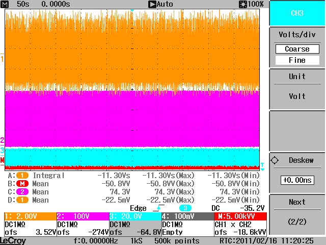
55 - not so brief - many moments in time - in fact, 50 seconds worth
Dear Reader,
Here's a sight for sore eyes. Fifty seconds of pure magic in one fell swoop. Enjoy. Much more to follow - but this little doozy took a cool 18 minutes to upload. It needs framing.
Kindst regards,
Rosie

Here's a sight for sore eyes. Fifty seconds of pure magic in one fell swoop. Enjoy. Much more to follow - but this little doozy took a cool 18 minutes to upload. It needs framing.
Kindst regards,
Rosie
Tuesday, February 15, 2011
54 - thinking aloud
Dear Reader,
We have been debating how to do the demonstration planned for month end. The idea is to present unequivocal proof of what classically would be seen as an anomalous result. Our options are fairly wide. We can show a very high wattage dissipated. But the values off our data dump vary from between any extreme of negative loss from the battery to 11 watts for the 44 watts dissipated. This is in line with our previous test results and more specifically in line with that well publicised replication. It's the fact that it varies at all that worries me. It will, possibly, become contended - and I would prefer it that the results are unequivocally anomalous. Surprisingly, or perhaps because the wattage dissipated is higher - there's also evidence of a quicker recharge to the batteries which, as measured drifted north - to end up about 1 volt higher after a little over a 2 hour run. But it is also a fact that the one reading varies from another and I'm not sure that I want to spend time debating the measurements.
I think what we will do is simply set the parameters to show the mean average of power delivered where all measurements relating to the delivery of the energy from the supply show negative values. This includes the mean average, the integral, and the math trace. These values are also consistently born out in the data dumps off our 200 MHz bandwidth and our 500 MHz bandwidth DSO's.
I'll be posting some preliminary updates here for that report. The down side is that we're dealing with smaller wattage levels again. But what I can do, after the demo, is show them the fuller range of benefits. I just want accreditation to be unarguable. And then - perhaps - just point at what still needs to be researched.
Kindest regards,
Rosemary
We have been debating how to do the demonstration planned for month end. The idea is to present unequivocal proof of what classically would be seen as an anomalous result. Our options are fairly wide. We can show a very high wattage dissipated. But the values off our data dump vary from between any extreme of negative loss from the battery to 11 watts for the 44 watts dissipated. This is in line with our previous test results and more specifically in line with that well publicised replication. It's the fact that it varies at all that worries me. It will, possibly, become contended - and I would prefer it that the results are unequivocally anomalous. Surprisingly, or perhaps because the wattage dissipated is higher - there's also evidence of a quicker recharge to the batteries which, as measured drifted north - to end up about 1 volt higher after a little over a 2 hour run. But it is also a fact that the one reading varies from another and I'm not sure that I want to spend time debating the measurements.
I think what we will do is simply set the parameters to show the mean average of power delivered where all measurements relating to the delivery of the energy from the supply show negative values. This includes the mean average, the integral, and the math trace. These values are also consistently born out in the data dumps off our 200 MHz bandwidth and our 500 MHz bandwidth DSO's.
I'll be posting some preliminary updates here for that report. The down side is that we're dealing with smaller wattage levels again. But what I can do, after the demo, is show them the fuller range of benefits. I just want accreditation to be unarguable. And then - perhaps - just point at what still needs to be researched.
Kindest regards,
Rosemary
54 - FLUKE 190-104 4CH 100MHz 1,25GS/s
Dear Reader,
Just a quick note. I had a few day's loan on a really wonderful little Fluke DSO that could show the waveform across the load and the shunt resistor simultaneously. What a wonderful little instrument. It is not compatible with my flash drive and unfortunately I was unable to give you copies of that waveform.
What was evident was a small phaseshift between the two but their essential shape is the same - both moving above and below zero. I'm hoping I can secure another one for our demo. Meanwhile I'll post the photos that I did - unfortunately also not that clear. I still need to upload them to photobucket.
Sorry we can't give more info here.
Kindest regards
Rosemary

Just a quick note. I had a few day's loan on a really wonderful little Fluke DSO that could show the waveform across the load and the shunt resistor simultaneously. What a wonderful little instrument. It is not compatible with my flash drive and unfortunately I was unable to give you copies of that waveform.
What was evident was a small phaseshift between the two but their essential shape is the same - both moving above and below zero. I'm hoping I can secure another one for our demo. Meanwhile I'll post the photos that I did - unfortunately also not that clear. I still need to upload them to photobucket.
Sorry we can't give more info here.
Kindest regards
Rosemary

53 - on resonance on our circuit
Dear Reader,
This is an attempt to explain the resonating cndition that is evident on our circuit. I'm not sure how 'classical' is this explanation. But it is certainly in line with what is seen and measured. And it is also in line with the 'thinking' which is now the preferred euphemism for 'thesis'. LOL.
The 'diagram' schematic has been included now. Technically the schematic should include a resistor and inductor in series but, as we're addressing the properties of inductance will leave it as it is.
Also, the waveform samples show a a triggering on the negative cycle. When this is combined with that resonating frequency it has very beneficial results to the co-efficient of performance. I'll add more on this later.
KIndest regards,
Rosemary
ON RESONANCE AND THE CIRCUIT CONFIGURATION TO ALLOW THIS AND AS IT RELATES TO THE POLARITY OF ELECTRIC CURRENT
The following assumptions are made. Magnetic fields comprise the material property of magnetic dipoles that are hidden from view as they exceed light speed and therefore, in a field condition, they are invisible. All magnetic fields obey an immutable imperative to move to a condition of best charge balance. Voltage is the measure of the potential difference in magnetic fields that are in a transitional stage of imbalance. Current flow comprises magnetic fields that move at 90 degrees to the applied voltage. Current flow moves to discharge potential difference from a voltage or supply source. Both current and voltage comprise magnetic dipoles in fields that are aligned in a sympathetic charge relationship to secure a balanced charge condition in their field.
Therefore, voltage is a measure of localised potential difference or magnetic imbalance. Current flow is a non-localised measure of the rate at which the voltage or potential difference is able to discharge that potential difference through a circuit. Therefore current flow relies on the material inductive and conductive conditions of a circuit path to enable its flow. Conversely voltage, as a localised measure of the material charge imbalance, can be regarded as a store of potential difference of electromagnetic energy.
FIGURE 1

Voltage can either be positive or negative depending on its orbital justification around circuit material components. Convention has determined that this is measured in relation to a zero reference where positive, above zero, would generate a current flow in a clockwise direction and, conversely, negative, below zero, would generate a current flow in an anti-clockwise direction. Therefore there is a consistency in the field distribution of charge, where the positive clockwise will lead with the positive of the field. And conversely, the negative anti-clockwise will lead with the negative of the field.
The function of the transistor in this circuit is to allow a small charge from a signal generator (or similar) onto the gate sufficient to block the path of current flow in the circuit. Therefore, if the flow of current from the signal generator to the gate is positive then, when a positive signal of sufficient strength is introduced to the circuit path, the transistor will block the positive flow of current from the supply battery. During this period the positive voltage supply source can no longer deliver a current flow and the circuit is, effectively open relative to that supply.
FIGURE 2

If the signal applied to the transistor gate is then changed to negative or neutral it will allow the flow of a positive current in the circuit. Conversely the gate will block any flow of current that leads with a negative charge. However, in this circuit configuration the transistor used has an internal body diode that allows the passage of current that is negative or that leads in an anti-clockwise direction with a negative charge. Effectively therefore the circuit is configured that it is intermittently open to a positive charge as is determined by the applied positive charge at the gate of the transistor. And it is permanently closed to allow all conditions of negative current flow through its body diode.
Therefore, provided only that there is a negative voltage induced as a consequence of the prior discharge of a positive current from a positive voltage then there will always be a path for the flow of that negative current enabled by that Zener body diode at the transistor switch.
When the applied signal charge at the gate defaults to negative charge, then there is nothing to prevent the flow of positive current from the potential difference across the circuit components. These collapsing, positive voltage fields generate a clockwise current flow that moves through the gate to complete their orbit at their respective localised terminals.
The amount of discharge relates precisely to the amount of current that, in turn, relates to the level of voltage that was first applied by the positive voltage supply sources including the supply and the inductive/conductive material of the circuit components. But when that potential difference is discharged it again collapses to zero and in changing it induces a reverse voltage or potential difference measured as a negative voltage. This is determined in line with Inductive Laws where changing electric fields induce a magnetic field. And changing magnetic fields induce an electric field.
A voltage collapsing to zero represents a changing magnetic field. This, in turn, develops an opposing voltage that is generated in anti phase and can be seen as a negative voltage. And this, in turn, induces an anti clockwise current flow that is able to move through the internal body diode, which, as mentioned, is sympathetically charged to permanently enable this current flow polarity.
The signal at the transistor gate changes to allow positive clockwise current flow from the battery through the circuit. A corresponding positive voltage is developed across the conductive and inductive circuit components. And this persists until the circuit is again opened by the imposition of a blocking positively biased charge at the gate. And so the cycle is repeated.
Therefore the resonance that is evident during the period when the gate signal is negative (bidirectional current flow) is also allowed only if there is the assumption of a dual charge property in the material of both voltage and current and if there is also a prior assumption of a material property in those magnetic fields. Only on the basis of this assumption can one then explain the evidence of resonance where the voltage is seen to persistently induce a counter phase voltage and its consequent current flow to discharge that voltage.
The level of resonance would be determined by the availability and size of path that is provided by the body diode during the discharge of negative current and by the resistance provided in circuit components. The negative path through the body diode would need to be sufficiently wide to allow for the unrestricted flow of current in the negative or anti-clockwise direction to secure that resonating condition. With this proviso, then the rate at which voltage collapses and regenerates, would be determined by the material where the voltage is localised. In the samples referenced it is evident that this occurs at approximately 1 MHz.
When the voltage on circuit components collapses, they induce a corresponding current flow that is seen in anti phase to the initiating supply source. In this circuit example the supply is a lead acid battery. Therefore, while open circuit conditions apply then a negative anti clockwise current flow will increase the potential difference at the supply thereby representing a recharge cycle. And the consequent and induced positive voltage will decrease the supply thereby representing a decrease of voltage to the supply. If the amount of current flow delivered during the negative cycle is in excess of the amount of current flow delivered during the positive cycle then there will be a net recharge to the battery supply source commensurate with that measured excess.
This is an attempt to explain the resonating cndition that is evident on our circuit. I'm not sure how 'classical' is this explanation. But it is certainly in line with what is seen and measured. And it is also in line with the 'thinking' which is now the preferred euphemism for 'thesis'. LOL.
The 'diagram' schematic has been included now. Technically the schematic should include a resistor and inductor in series but, as we're addressing the properties of inductance will leave it as it is.
Also, the waveform samples show a a triggering on the negative cycle. When this is combined with that resonating frequency it has very beneficial results to the co-efficient of performance. I'll add more on this later.
KIndest regards,
Rosemary
ON RESONANCE AND THE CIRCUIT CONFIGURATION TO ALLOW THIS AND AS IT RELATES TO THE POLARITY OF ELECTRIC CURRENT
The following assumptions are made. Magnetic fields comprise the material property of magnetic dipoles that are hidden from view as they exceed light speed and therefore, in a field condition, they are invisible. All magnetic fields obey an immutable imperative to move to a condition of best charge balance. Voltage is the measure of the potential difference in magnetic fields that are in a transitional stage of imbalance. Current flow comprises magnetic fields that move at 90 degrees to the applied voltage. Current flow moves to discharge potential difference from a voltage or supply source. Both current and voltage comprise magnetic dipoles in fields that are aligned in a sympathetic charge relationship to secure a balanced charge condition in their field.
Therefore, voltage is a measure of localised potential difference or magnetic imbalance. Current flow is a non-localised measure of the rate at which the voltage or potential difference is able to discharge that potential difference through a circuit. Therefore current flow relies on the material inductive and conductive conditions of a circuit path to enable its flow. Conversely voltage, as a localised measure of the material charge imbalance, can be regarded as a store of potential difference of electromagnetic energy.
FIGURE 1

Voltage can either be positive or negative depending on its orbital justification around circuit material components. Convention has determined that this is measured in relation to a zero reference where positive, above zero, would generate a current flow in a clockwise direction and, conversely, negative, below zero, would generate a current flow in an anti-clockwise direction. Therefore there is a consistency in the field distribution of charge, where the positive clockwise will lead with the positive of the field. And conversely, the negative anti-clockwise will lead with the negative of the field.
The function of the transistor in this circuit is to allow a small charge from a signal generator (or similar) onto the gate sufficient to block the path of current flow in the circuit. Therefore, if the flow of current from the signal generator to the gate is positive then, when a positive signal of sufficient strength is introduced to the circuit path, the transistor will block the positive flow of current from the supply battery. During this period the positive voltage supply source can no longer deliver a current flow and the circuit is, effectively open relative to that supply.
FIGURE 2

If the signal applied to the transistor gate is then changed to negative or neutral it will allow the flow of a positive current in the circuit. Conversely the gate will block any flow of current that leads with a negative charge. However, in this circuit configuration the transistor used has an internal body diode that allows the passage of current that is negative or that leads in an anti-clockwise direction with a negative charge. Effectively therefore the circuit is configured that it is intermittently open to a positive charge as is determined by the applied positive charge at the gate of the transistor. And it is permanently closed to allow all conditions of negative current flow through its body diode.
Therefore, provided only that there is a negative voltage induced as a consequence of the prior discharge of a positive current from a positive voltage then there will always be a path for the flow of that negative current enabled by that Zener body diode at the transistor switch.
When the applied signal charge at the gate defaults to negative charge, then there is nothing to prevent the flow of positive current from the potential difference across the circuit components. These collapsing, positive voltage fields generate a clockwise current flow that moves through the gate to complete their orbit at their respective localised terminals.
The amount of discharge relates precisely to the amount of current that, in turn, relates to the level of voltage that was first applied by the positive voltage supply sources including the supply and the inductive/conductive material of the circuit components. But when that potential difference is discharged it again collapses to zero and in changing it induces a reverse voltage or potential difference measured as a negative voltage. This is determined in line with Inductive Laws where changing electric fields induce a magnetic field. And changing magnetic fields induce an electric field.
A voltage collapsing to zero represents a changing magnetic field. This, in turn, develops an opposing voltage that is generated in anti phase and can be seen as a negative voltage. And this, in turn, induces an anti clockwise current flow that is able to move through the internal body diode, which, as mentioned, is sympathetically charged to permanently enable this current flow polarity.
The signal at the transistor gate changes to allow positive clockwise current flow from the battery through the circuit. A corresponding positive voltage is developed across the conductive and inductive circuit components. And this persists until the circuit is again opened by the imposition of a blocking positively biased charge at the gate. And so the cycle is repeated.
Therefore the resonance that is evident during the period when the gate signal is negative (bidirectional current flow) is also allowed only if there is the assumption of a dual charge property in the material of both voltage and current and if there is also a prior assumption of a material property in those magnetic fields. Only on the basis of this assumption can one then explain the evidence of resonance where the voltage is seen to persistently induce a counter phase voltage and its consequent current flow to discharge that voltage.
The level of resonance would be determined by the availability and size of path that is provided by the body diode during the discharge of negative current and by the resistance provided in circuit components. The negative path through the body diode would need to be sufficiently wide to allow for the unrestricted flow of current in the negative or anti-clockwise direction to secure that resonating condition. With this proviso, then the rate at which voltage collapses and regenerates, would be determined by the material where the voltage is localised. In the samples referenced it is evident that this occurs at approximately 1 MHz.
When the voltage on circuit components collapses, they induce a corresponding current flow that is seen in anti phase to the initiating supply source. In this circuit example the supply is a lead acid battery. Therefore, while open circuit conditions apply then a negative anti clockwise current flow will increase the potential difference at the supply thereby representing a recharge cycle. And the consequent and induced positive voltage will decrease the supply thereby representing a decrease of voltage to the supply. If the amount of current flow delivered during the negative cycle is in excess of the amount of current flow delivered during the positive cycle then there will be a net recharge to the battery supply source commensurate with that measured excess.
Sunday, February 13, 2011
52 - the poynt of no return
Dear Readers,
Greatly amused at the even greater nonsense being referenced on our old 'erstwhile' locked thread. I see that the all the license of the 'rant room' is now liberally extended to any reference to me or my work. One would almost think that Poynty still intends to 'debunk' this circuit rather than submit it to serious analysis. I'm glad of this evidence of partiality. It reminds me that I must never actually refer to them in any serious context whatsoever.
And it also seems that the only reason that the thread was locked was because I dared defend myself against Glen - aka Fuzzy. He's that well known dyslexic that tried so hard to steal the invention by multiple unsubstantiated allegations against my good name. He struggles on - with a rather ham fisted attempt at wit. And now with the full endorsement of Poynty the Partial. And because they're all just nasty old men they all cackle away. Quite endearing in a sort of twisted way. Anyway - they may all post - apparently - in as defamatory a tone as they require. Just as long as I don't defend myself. Also just as well as it seems that this technology is progressed as much by notoriety as by serious research. And I only care that it's progressed.
And this is for that short but noisy list of toothless 3rd school 'nay sayers'. You guys have got a serious problem. You still need to explain how it is that we're getting all that 'ringing' if that's how you want to refer to it. I'm looking forward to an explanation that is not couched in such ponderous attempts at wit.
And Poynty. I think the public generally would appreciate it if you could 'debunk' the LT Joule Thief variant by showing similar waveforms - at LEAST. Anything short of that and we're all rather inclined to think that your experimental aptitudes are bereft. You've been posed some questions by Harvey the Wooly Worder - who has presented you with some uncharacteristically articulate posers. Let's see you wriggle your way around them. And PLEASE. Give us some relief in CLEAR SCHEMATICS. Where are your probes positioned and ON WHAT CIRCUIT and around what components? If you need to learn how it's done ask Harvey. Your references are somewhat confusing - compounded by your liberal use of inappropriate acronyms. Not good Poynty Point. Not good at all.
Kindest regards notwithstanding
Rosie
Greatly amused at the even greater nonsense being referenced on our old 'erstwhile' locked thread. I see that the all the license of the 'rant room' is now liberally extended to any reference to me or my work. One would almost think that Poynty still intends to 'debunk' this circuit rather than submit it to serious analysis. I'm glad of this evidence of partiality. It reminds me that I must never actually refer to them in any serious context whatsoever.
And it also seems that the only reason that the thread was locked was because I dared defend myself against Glen - aka Fuzzy. He's that well known dyslexic that tried so hard to steal the invention by multiple unsubstantiated allegations against my good name. He struggles on - with a rather ham fisted attempt at wit. And now with the full endorsement of Poynty the Partial. And because they're all just nasty old men they all cackle away. Quite endearing in a sort of twisted way. Anyway - they may all post - apparently - in as defamatory a tone as they require. Just as long as I don't defend myself. Also just as well as it seems that this technology is progressed as much by notoriety as by serious research. And I only care that it's progressed.
And this is for that short but noisy list of toothless 3rd school 'nay sayers'. You guys have got a serious problem. You still need to explain how it is that we're getting all that 'ringing' if that's how you want to refer to it. I'm looking forward to an explanation that is not couched in such ponderous attempts at wit.
And Poynty. I think the public generally would appreciate it if you could 'debunk' the LT Joule Thief variant by showing similar waveforms - at LEAST. Anything short of that and we're all rather inclined to think that your experimental aptitudes are bereft. You've been posed some questions by Harvey the Wooly Worder - who has presented you with some uncharacteristically articulate posers. Let's see you wriggle your way around them. And PLEASE. Give us some relief in CLEAR SCHEMATICS. Where are your probes positioned and ON WHAT CIRCUIT and around what components? If you need to learn how it's done ask Harvey. Your references are somewhat confusing - compounded by your liberal use of inappropriate acronyms. Not good Poynty Point. Not good at all.
Kindest regards notwithstanding
Rosie
Saturday, February 12, 2011
52 - resonance on an open circuit
Dear Reader,
For those who are interested - here's a close-up of some of the ringing. Of possible interest is some explanation that this can happen during the period when the circuit is ostensibly open. The clue is in the negative triggering at the gate.
I'll be including that explanation in my report.
Kindest regards,
Rosemary
YELLOW TRACE CHANNEL 1 SHUNT @ 0.25 Ohm
PINK TRACE CHANNEL 2 BATTERY
BLUE TRACE GATE OF MOSFET IRFPG50


For those who are interested - here's a close-up of some of the ringing. Of possible interest is some explanation that this can happen during the period when the circuit is ostensibly open. The clue is in the negative triggering at the gate.
I'll be including that explanation in my report.
Kindest regards,
Rosemary
YELLOW TRACE CHANNEL 1 SHUNT @ 0.25 Ohm
PINK TRACE CHANNEL 2 BATTERY
BLUE TRACE GATE OF MOSFET IRFPG50


Subscribe to:
Posts (Atom)